Silicon Motion SM2258XT and SM2259XT MP Tool Guide: ROM Mode, RDT, and ISP
A practical SM2258XT, SM2259XT, SM2259XT2, and SM2259XT3 workflow covering Flash ID, CH/CE checks, RDT bad-block testing, final ISP initialization, and common failures.
Silicon Motion SM2258XT, SM2259XT, SM2259XT2, and SM2259XT3 controllers are common in SATA, mSATA, and M.2 SATA SSDs. If a drive disconnects, reports the wrong capacity, cannot be partitioned, or has damaged firmware, a matching Silicon Motion mass-production tool may reinitialize it when the existing data can be discarded.
These controllers use similar tool interfaces and workflows, but similar model names do not make firmware or configurations interchangeable. The MP tool must match the complete controller model, NAND generation or Flash ID, channel and CE layout, and PCB design.
Data warning: RDT, ISP, and mass-production operations write to NAND and may erase the entire drive. Do not follow this procedure when files must be recovered. Start with the decision workflow for a severely failed SSD.
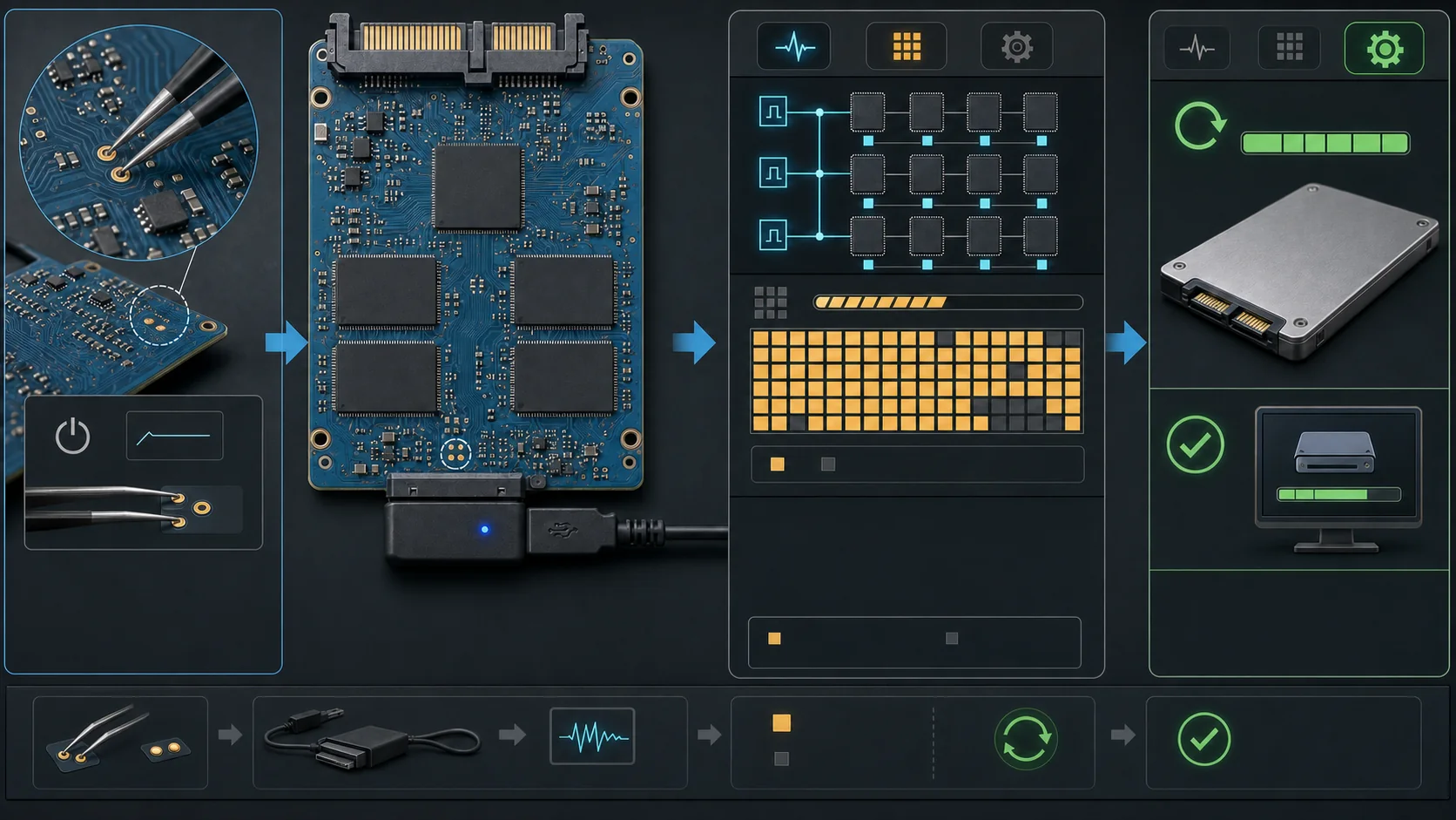
Scope
This guide provides a general framework for:
Menu labels, passwords, Pretest numbers, and RDT options vary between MPTool releases. This guide explains the purpose of each stage rather than prescribing one fixed configuration for every SSD.
What you need
- An isolated Windows repair computer: this reduces the risk of selecting another drive and makes drivers and security easier to control.
- A stable connection: direct motherboard SATA is useful when supported. ROM-mode cases often use an ASM1153E or JMS578 USB-to-SATA bridge, but compatibility must be tested for the specific tool and controller.
- Fine tweezers or a reliable shorting tool: use them only on confirmed ROM test points.
- A matching MPTool archive: search the site’s MP tool catalog by controller and NAND, then verify the filename, notes, and SHA-256.
- A hardware record: photograph both PCB sides and preserve the controller marking, NAND markings, original capacity, product label, and board number.
Do not run mass production through a front-panel USB port, hub, or loose extension lead. A power or connection loss can leave the controller in a more difficult state.
1. Identify the controller and NAND
Open the SSD and read the complete marking on the square controller package. SM2258XT and SM2258H are different designs; SM2259XT2 and SM2259XT2G should not be treated merely as “2259” either.
Record the marking on every NAND package. When the exact part is known, verify its vendor, generation, die structure, capacity, and Flash ID. For remarked, sanded, or unknown NAND, first read its Flash ID through the controller.
Reading the Flash ID of unknown NAND
- Select a trusted tool release that explicitly supports the controller family.
- Connect the SSD in ROM or engineering mode.
- After detection, open the page commonly labeled
1024M,SSD Information, or a similar name. - Record the complete Flash ID, typically six bytes, rather than only the first bytes.
- Identify the NAND generation from that ID and select an MPTool release whose Flash database contains it.
“Download a random tool first” is unsafe. A mismatched driver, DLL, or firmware can misidentify the hardware. Even a tool used only for reading IDs should match the controller family, and Start should not be pressed before the configuration is understood.
2. Enter ROM mode and detect the device
Damaged firmware may prevent the SSD from appearing in normal mode. ROM test points on the PCB can force the controller to boot from its internal ROM.
Use this sequence:
- Fully disconnect the SSD and computer interface.
- Confirm the ROM test points from a matching PCB number or reliable repair reference; do not guess from a
ROMorJP1label alone. - Short only the specified test points.
- Keep them shorted while connecting the SSD through the verified bridge or interface.
- Open MPTool and use Search Device or rescan the ports.
- Remove the tweezers when the tool detects the ROM-mode device, following the board-specific procedure.
Do not keep the points shorted throughout the operation unless the board documentation explicitly requires it. A wrong short can damage a supply rail or the controller.
3. Inspect Flash ID, channels, and CE first
Do not press Start as soon as the device appears. Open SSD Information or 1024M and check:
- whether every NAND channel is present;
- whether the CE count under CH0, CH1, and other channels matches the physical layout;
- whether each complete Flash ID is present and consistent;
- whether any entry is blank, all zero, duplicated unexpectedly, or reports CE Error;
- whether the reported controller, NAND type, and capacity are plausible.
A CE error can be caused by failed NAND, poor soldering, a controller-channel fault, PCB routing or power, or simply the wrong Flash database. Check the hardware and tool version before hiding the symptom by disabling a CE.
Some tools allow a symmetric CH/CE subset to be selected so a drive with failed NAND can operate at reduced capacity. This is a degraded repair. Attempt it only when the topology is understood, the resulting capacity is calculated correctly, and the whole address space can be validated. An asymmetric or incorrect layout can create false capacity and corrupt data.
4. Unlock and build the configuration
On some older releases, open Settings, choose Edit Config, and enter a password. The specific build described by the source article uses two spaces, but other releases differ. Follow the documentation included with that archive.
Copy the original configuration file before editing these areas:
1. Automatic NAND detection
Auto may return several candidate NAND definitions. Do not mechanically select the first item. Compare the complete Flash ID, die structure, page/block geometry, and expected capacity. If every candidate is wrong, use another MPTool release with the correct Flash database.
2. Product identity
The product name, serial number, and firmware label can be set for repair use, but should not impersonate factory identity. Keep the original label photograph and a repair record that identifies the tool and configuration used.
3. Capacity
Use Auto as a starting point only when every CE is healthy and the hardware is complete. If CEs have been removed or more spare area is required, calculate capacity from the actual NAND layout rather than changing only the displayed number.
4. NAND frequency
A lower interface frequency can sometimes help marginal or older NAND complete initialization. It improves signaling tolerance; it does not repair worn media. If errors continue at a conservative frequency, investigate the NAND, soldering, and power rather than retrying indefinitely.
5. Understand Pretest, ignore options, and RDT
The meaning of a Pretest number can vary by release. A workflow reported in the source uses Pretest 1 before the first RDT, followed by the mode that consumes the RDT bad-block table—shown as Pretest 3 in some builds—for the final ISP. Check the documentation for the exact tool.
Treat ignore options as exceptions
- Ignore grade distinction: may allow mixed NAND grades, but reduces consistency.
- Ignore Tran ADJ: use only when the failure has been confirmed as a training-compatibility issue.
- Ignore errors or skip tests: can produce a PASS result while leaving unstable writes or false capacity.
These options are not the default response to an error. Save the code and check the Flash database, frequency, soldering, and CH/CE configuration first.
RDT versus ISP
| Mode | Purpose | State afterward |
|---|---|---|
| RDT | Writes test patterns and reads them back to discover and mark bad blocks | Normally requires another standard ISP run before the SSD can be used as a normal disk |
| ISP / normal MP | Writes the final firmware and configuration and creates the operating mapping | Should report a normal model and capacity after a full power cycle |
RDT writes the entire NAND and can take a long time. Duration depends on capacity, NAND speed, selected frequency, and bad-block count. Do not use a fixed estimate such as “1.5 hours for 512 GB” as the completion signal.
6. Run RDT
Start RDT only after the Flash IDs, channels, CEs, and basic configuration are plausible:
- Enable
RDT Test, openRDT Setting, and verify loops, bad-block thresholds, and test scope. - Save the configuration, return to the port list, confirm the correct target, and press Start.
- If that tool release expects the SSD to perform RDT from standalone power, disconnect it safely and connect it to a stable supply exactly as documented.
- Wait for a definite completion state; do not interrupt power.
- Reopen the same tool version, reconnect the SSD, and read the RDT result and bad-block statistics.
Lower USB current, an inactive LED, or cooler NAND packages are only secondary clues. They do not replace the tool’s status, and touching NAND to judge temperature can cause burns and misinterpretation.
If RDT fails, inspect the channel, CE, and bad-block count. Repeated failure usually indicates a NAND, soldering, power, or controller problem. Raising limits or ignoring errors does not make the media reliable.
7. Disable RDT and perform the final ISP
After a successful RDT, a normal ISP run is usually still required:
- Select the tool’s mode that uses the RDT bad-block table; this is
Pretest 3in some releases. - Clear the
RDT Testoption. - Recheck NAND, capacity, CH/CE layout, and firmware.
- Save the configuration and start the final run.
- After PASS, fully remove power and reconnect the SSD.
Without the final ISP, the controller may remain in a test state and fail to present a normal disk for partitioning.
8. Repartition and validate everything
After initialization, confirm the physical capacity in Windows Disk Management, then initialize and partition the disk. At minimum:
- confirm that model, capacity, and firmware remain stable;
- inspect SMART with CrystalDiskInfo, while remembering that MP initialization may reset it;
- run a short benchmark to detect severe throttling or freezes;
- write and read back the entire usable capacity with urwtest, H2testw, F3, or an equivalent verifier;
- perform several complete power removals and cold boots;
- preserve the MPTool log, RDT result, final configuration, and tool version.
Any full-capacity error, disconnect, or capacity change means the repair is not complete. A drive repaired by dropping CEs, mixing NAND grades, or hiding many bad blocks should be treated as experimental hardware, not storage for important data.
Troubleshooting
MPTool cannot find the device
Verify that the ROM points match the exact PCB, the bridge passes vendor commands, the driver is correct, and the controller is powered. Remove power before changing ports; do not move tweezers on a live board.
The controller appears but there is no Flash ID
Possible causes include an unsupported Flash database, NAND power failure, poor soldering, an incorrect CE layout, or failed NAND. Try a matching tool build and inspect the hardware before writing firmware.
Auto lists several NAND definitions
Filter by the complete Flash ID, die/CE structure, and capacity. Stop if these cannot be verified; do not select the first item solely because it appears first.
RDT passes but the final ISP fails
Check that RDT is disabled, the correct RDT bad-block-table mode is selected, the final firmware supports the NAND, and the edited configuration was actually saved.
The repaired capacity is half the original
Check whether a CE was disabled, the wrong channel group was selected, or the configuration describes a smaller NAND topology. Validate the entire resulting disk; a partition-table edit cannot restore physical capacity that the controller does not expose.
Source and limitations
This guide is a rewritten and safety-expanded version of the original LCB/量产帮 SM2258XT tutorial, connected to this site’s controller and tool indexes. The original screenshots and parameters describe a particular MPTool build. Other MPTool releases, NAND generations, PCBs, and bridge chips may require different settings.