SSD Not Detected or Unable to Format? A Practical MP Tool Repair Workflow
A structured workflow for severe SSD failures: decide whether the data matters, identify the controller and NAND, enter engineering mode, select a matching MP tool, and validate the entire drive.
An SSD that is not detected, reports the wrong capacity, cannot be partitioned or formatted, or causes freezes and blue screens during I/O is not necessarily ready for disposal. A factory mass-production (MP) tool may restore a drive when its controller firmware, mapping tables, or Flash configuration has been damaged.
MP repair is not data recovery. It normally rebuilds firmware and Flash mappings and erases everything on the drive. There is no reliable basis for promising that it will repair “90% of failures.” Physical damage, a failed controller, power faults, and heavily worn NAND may be impossible to repair.
Make this decision first: If the data matters, stop powering on, formatting, updating firmware, or running MP tools. Send the drive to a qualified chip-level recovery service. Continue only when the data can be discarded and the goal is to attempt to return the hardware to service.
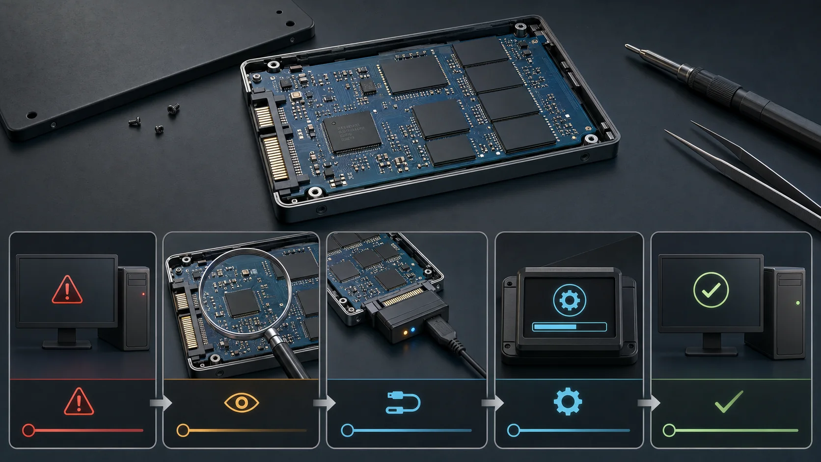
Failures that may be suitable for MP repair
MP repair is most relevant when:
- the BIOS or operating system occasionally finds the device, but its model, capacity, or serial number is wrong;
- the drive cannot be initialized, partitioned, or formatted;
- the firmware is in a protected state and exposes a factory name, default name, or abnormal capacity;
- reads and writes still cause disconnects or timeouts after cables, power, and ports have been ruled out;
- the controller can enter ROM, boot, or engineering mode, and a tool with the correct Flash support is available.
If the PCB is burned, the controller is cracked or abnormally hot, the NAND packages are physically damaged, or the device has no electrical response, investigate the hardware first instead of repeatedly running MP software.
Workflow at a glance
- Rule out port, power, cable, and adapter faults.
- Open the drive and record the controller, NAND, DRAM, and PCB details.
- Find an MP tool that matches the controller, Flash, and board configuration.
- Enter ROM or engineering mode according to the exact PCB definition.
- Run initialization over a stable connection.
- Repartition the drive and validate its full capacity, I/O, and stability.
1. Rule out external faults first
Before opening the drive, cross-check the basics:
- replace the SATA data cable, power lead, USB cable, and computer port;
- connect a SATA SSD directly to a motherboard SATA port when possible;
- confirm the symptom on another computer or operating system;
- if the drive can still be read reliably, make a complete backup before running benchmarks, surface scans, or repairs;
- check whether only the partition table or file system is damaged. When the capacity is correct and reads are stable, prefer a read-only backup or partition recovery over MP initialization.
This prevents a power issue, cable, or ordinary USB enclosure from being mistaken for an SSD failure.
2. Identify the controller, DRAM, NAND, and PCB
Disconnect power, take electrostatic precautions, open the enclosure, and photograph both sides of the PCB. Record:
- Controller: determines the MP tool vendor and controller family.
- Flash/NAND packages: determine whether a tool version contains the required NAND definitions.
- DRAM cache: some designs require the correct memory type and capacity in their configuration.
- PCB number and hardware revision: test points, power design, and firmware may differ even with the same controller.
- Original label: preserve the product model, capacity, serial number, and firmware version.
For example, an SMI SM2246EN controller with Micron NAND requires a tool version that explicitly supports both SM2246EN and the installed Micron NAND. Use the controller catalog and MP tool catalog as starting points. A matching controller name alone does not prove compatibility.
Newer is not always better
A controller family often has several MP tool releases. A recent stable release is a reasonable place to begin research, but support for older NAND may exist only in an older Flash database. New releases may also remove legacy definitions. Check at least:
- the complete controller model and revision;
- NAND markings, Flash ID, die count, and CE configuration;
- whether the device is SATA, mSATA, M.2 SATA, or NVMe;
- tool documentation, configuration files, and credible reports involving the same hardware.
Verify archives before execution, use an isolated repair computer, and preserve the original tool configuration.
3. Enter ROM or engineering mode
When controller firmware is badly damaged, the MP tool may not see the drive in normal mode. The controller then has to boot in ROM or engineering mode as defined by that specific PCB.
Some boards label nearby test points ROM, ROM MODE, JP1, J1, or J3, but these labels are not a universal standard. Two boards using the same controller may have completely different shorting points.
Use this safe sequence:
- Disconnect power from the SSD.
- Confirm the test points from a matching board number, repair reference, or schematic. Never guess from appearance.
- Short only the specified points during power-on detection, following the tool or board instructions.
- Remove the short when the computer or MP tool detects the engineering-mode device, if the procedure says to do so.
- Keep metal tools away from the PCB while initialization is running.
Shorting the wrong pads can short a supply rail, destroy the controller, or make the failure worse. Stop when no reliable board-level reference is available.
4. Choose the correct bridge and connection
MP tools may depend on a particular USB-to-SATA bridge, driver, or transfer mode. An ordinary enclosure that reads a healthy disk does not necessarily pass ROM-mode or vendor-specific commands. A dedicated MP adapter is usually more predictable.
Connection guidelines:
- prefer a rear motherboard USB port or a native motherboard interface;
- avoid hubs, front-panel ports, and long extension cables;
- keep power stable and do not disturb connectors during the operation;
- use an appropriate mSATA adapter for an mSATA SSD;
- M.2 SATA and M.2 NVMe devices can look similar but use different protocols and adapters;
- NVMe controller repair is different from SATA mass production. Putting an NVMe SSD in a USB enclosure does not make SATA MP instructions applicable.
Older field reports often mention JM20329C/D, ASMT2105, INIC-1608L, INIC-1618L, or ASM1153E bridges. Treat these as search terms for historical cases, not universal recommendations. Confirm the exact bridge suffix, firmware, driver, target controller, and engineering-mode support before buying. Some ordinary JM20329E devices support only limited operations while the SSD is already working normally.
5. Run the MP tool
Interfaces vary significantly between controller vendors, but the general sequence is similar:
- Install required drivers on an isolated Windows repair environment and run the tool as administrator.
- Make sure the detected target is the failed SSD, not another drive in the computer.
- Save the detected identity, Flash ID, current configuration, and any available logs.
- Select settings that match the NAND, capacity, channels, CE count, and DRAM configuration.
- Run the tool’s scan or detection stage before starting initialization or mass production.
- Save the complete log, including tool version, configuration, and error codes.
- After completion, fully remove power and reconnect the drive to verify its model and capacity.
Do not cycle through random firmware, capacity, or Flash settings without evidence. A wrong configuration can create false capacity, repeated disconnects, corrupt writes, or a drive that no longer enters engineering mode.
Some controllers have no public tool
Full factory tools for some Samsung and Marvell controllers are generally restricted to authorized manufacturers, and public support varies by generation. Some Phison controllers have public tools, while others can be recovered only when firmware, platform, and NAND match exactly. Never force firmware intended for another model.
If the device still accepts ATA or NVMe secure-erase commands, a vendor-approved secure erase may clear some logical faults. It also destroys all data and cannot repair failed hardware.
6. Validate the drive after a successful run
A PASS result means only that the tool completed its workflow. It does not prove that the SSD is reliable. Perform at least these checks:
- Repartition: initialize the disk as GPT or MBR in Windows Disk Management and create a partition. Modern Windows normally provides 4K alignment automatically; verify it when using third-party software.
- Inspect identity and SMART: use CrystalDiskInfo or the vendor utility to check model, capacity, firmware, and SMART. MP initialization may reset SMART, so normal-looking values do not prove that the NAND is healthy.
- Run a short performance check: use AS SSD Benchmark or an equivalent tool to detect obviously abnormal speed.
- Write and verify the entire capacity: use urwtest, H2testw, F3, or another full-capacity verifier to write all available space and read it back byte for byte.
- Power-cycle repeatedly: perform several clean shutdowns, full power removals, and cold boots, watching for disconnects, freezes, or capacity changes.
- Continue monitoring: review new bad blocks, ECC errors, and tool logs. If full-drive verification fails, stop treating the drive as reliable storage instead of merely creating a smaller partition.
Even after it passes, a repaired SSD should not hold the only copy of important data. Use it as an experimental or non-critical temporary drive and maintain a complete backup.
Common results and next steps
| Result | Recommended next step |
|---|---|
| The device is never detected in engineering mode | Recheck power, connection, test points, and controller hardware; do not guess with random firmware. |
| The controller is detected but no Flash is found | Check NAND power, soldering, Flash ID, and tool version; the NAND may be physically damaged. |
| Initialization reports an unsupported Flash or configuration error | Use a version or configuration that explicitly contains that NAND definition; do not force the process. |
| The run passes but capacity is wrong | Recheck channels, CE, die count, capacity, and reserved-space settings, then verify the entire disk again. |
| Full-capacity verification fails or the drive still disconnects | Treat the repair as failed or the medium as unreliable; replace the drive and do not store data on it. |
Summary
Repairing a severely failed SSD is not simply a matter of finding software and pressing Start. The controller, NAND, PCB, bridge, tool version, and configuration all have to match, and the entire capacity must be tested after initialization.
Do not run MP tools when the data matters. When the data can be discarded, MP repair is a reasonable attempt, but its success depends on the failure mode, hardware condition, and tool compatibility. If the test points, firmware, or Flash parameters cannot be verified, stopping is safer than guessing.